

 Structural analysis for assemblies with SOLIDWORKS Simulation enables engineers to efficiently analyze product behavior under mechanical conditions taking into account the physical relationships between the parts of the structure to ensure high quality, performance, and safety.
Tightly integrated with SOLIDWORKS CAD, structural analysis of assemblies can be a regular part of your design process, reducing the need for costly prototypes, eliminating rework and delays, and saving time and development costs.
Assembly Structural Analysis Overview
Every product is made of several parts or bodies. Defining how these parts interact and connect to each other is crucial for an accurate structural simulation during the product development process.
Contacts
SOLIDWORKS Simulation supports contact conditions for studies of assemblies and multi-bodies. The contact settings describe the interaction between part boundaries that are initially contacting or come into contact during loading. To accurately describe these interactions, SOLIDWORKS Simulation offers several types of contacts, such as:
- Bonded contact conditions to simulate entities as if they were welded
- Node-to-node, surface-to-surface conditions to prevent entities interference, but allows gaps to form
- Self-contact conditions for contact between faces of a body or part in large deflection analysis
- Shrink Fit, to simulate Shrink Fit between two bodies
- Virtual Wall to define contact between an entity and a virtual wall
- Thermal contact resistance to simulate a thin layer of epoxy by its resistivity
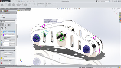
To enable fast definition of contact for large assemblies, SolidWorks Simulation automatically detects contact sets for touching faces or non-touching faces within a defined clearance.
With an intuitive color code, engineers can inspect all contacts created in the model with the Contact Visualization Plot. This tool enables you to easily understand how an assembly has been defined for structural simulation.
 Unconstrained Bodies
In an assembly analysis, users define contact and boundary conditions to accurately describe the environment and real world conditions of the product design.
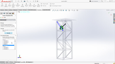
SOLIDWORKS Simulation guides product engineers through the analysis settings with the Unconstrained Bodies detection tool so they can verify that bodies are sufficiently constrained.
In a static study, users can view animations of the model based on the active degrees of freedom, and easily identify bodies that are under-constrained before running a simulation.
 Connectors
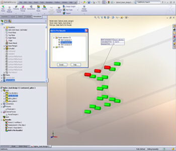
Products are also made with physical connections, such as bolts, springs, and welds between the parts of the assembly. SolidWorks Simulation offers sophisticated representations of these connections that simulate their behavior without having to create the detailed geometry. A connector is a mechanism that defines how an entity is connected to another entity or to the ground, such as: bolt, spring, pin, edge and spot weld and bearing.
Powerful tools such as the Safety Check empower engineers to validate if the connections will sustain the applied loads or if these connectors need resizing for performance and quality.
To speed up the simulation setup and leverage the 3D CAD data, product engineers can automatically convert SolidWorks Toolbox fasteners that exist in a model to Simulation bolt connectors. Automatically the bolt connections are defined with their properties, such as location, diameter, and materials.
 Submodeling
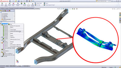
For an assembly with a large number of parts or bodies, the unique and powerful submodeling feature of SolidWorks Simulation Professional allows users to improve the results at critical areas without having to rerun the analysis for the whole model. Refining the mesh for a selected portion of the model and/or defining connectors for this portion and rerunning the analysis only for the submodel saves computation time during the product development process.