

The challenge of CADD*(Computer Aided Drafting and Design) is to digitize the pencil. After all a manual Drafter could draw any detail that was required, or in other cases, not draw unnecessary details that would confuse the drawing.
With a 3D model in SOLIDWORKS, generating drawing views is easy. In fact, too easy. As a result many drafters add extra pictorial and isometric views to their drawing because they are essentially ‘free’ as a result of the 3D model. While this can help to communicate the part or assembly, the manual Drafter rarely had the time necessary to generate these extra technical illustration views, and in most cases it was simply not necessary.
Unquestionably the 3D model gives us a lot of great information, however it poses another problem, information overload. For example if you need to make a section view through a complex part or assembly, you will notice that the important details can get easily buried in all the extraneous information present in the model. For example, take this excellent Eiffel Tower model created by Renato Nenadic posted on GrabCAD for you to download and enjoy. Suppose we take a section view of this Tower from the top looking down*(click on the images below to open a vectorized PDF, then zoom in with CTRL+Scroll):

The resulting section view on the drawing is perfectly complete. In fact it is showing all the cross members and other unnecessary detail all the way down to the base, as it is all a part of the model. The primary reason for the section view is to show details of the weldment structural members at the top of the tower, but as shown here can be difficult to see.

However there are a few things that you can do to address this issue. Your first option is to use the setting called ‘Section Depth‘, which can be defined by a distance or to a point on the model.
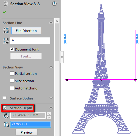
This setting tells SOLIDWORKS to discard all the model information that is beyond that selected point or distance. The end result is a cleaner section that has been trimmed down, which would also give the drafter more room on the drawing that would allow for optional scaling of the section view for even more clarity.

Or your other option is to select the ‘Slice Section’ setting, which will only display the faces, or surfaces of the structural members, that were actually cut by the Section line.

Thereby discarding the rest of the model. And this is what the result of the slice section looks like, again allowing the drafter to scale the view accordingly.

Happy Drafting…