


Easily create more accurate submodel studies for specific areas within your design that automatically utilize loads and boundary conditions applied to the full 3D model using SolidWorks Simulation submodel analysis.
Submodeling Study Overview
Submodeling is based on the St. Venant's principle which states that the stresses reasonably distant from an applied load on a boundary are not significantly altered if this load is changed to a statically equivalent load. The innovative Submodeling study technique of SolidWorks Simulation enables you to accurately test large and complex 3D models by performing precise simulation analysis for specific areas of interest faster and more efficiently.
To determine the stresses and deformations on these parts, you can:
- Refine the mesh for a selected portion of the model and rerun the analysis only for the submodel, saving computation time as well as improving the accuracy of the simulation
- Add new connectors, such as bolt connectors, between parts of the submodel
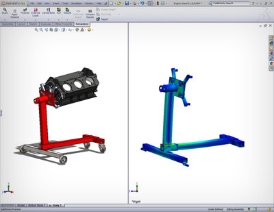 Linear stress analysis with SOLIDWORKS Simulation enables designers and engineers to quickly and efficiently validate quality, performance, and safety—all while creating their design.
Tightly integrated with SOLIDWORKS CAD, linear stress analysis using SOLIDWORKS Simulation can be a regular part of your design process, reducing the need for costly prototypes, eliminating rework and delays, and saving time and development costs.
Linear Stress Analysis Overview
Linear stress analysis calculates the stresses and deformations of geometry given three basic assumptions:
- The part or assembly under load deforms with small rotations and displacements
- The product loading is static (ignores inertia) and constant over time
- The material has a constant stress strain relationship (Hooke’s law)
SOLIDWORKS Simulation uses finite element analysis (FEA) methods to discretize design components into solid, shell, or beam elements and uses linear stress analysis to determine the response of parts and assemblies due to the effect of:
- Forces
- Pressures
- Accelerations
- Temperatures
- Contact between components
- Loads can be imported from thermal, flow, and motion Simulation studies to perform multiphysics analysis.
In order to carry out stress analysis, component material data must be known. The standard SOLIDWORKS CAD material database is pre-populated with materials that can be used by SOLIDWORKS Simulation, and the database is easily customizable to include your particular material requirements.
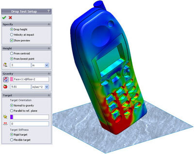 Find out quickly and efficiently how dropping a product onto a “floor” will affect its structural integrity using drop test analysis with SOLIDWORKS Simulation. Understanding impact strength is an important consideration to ensure an adequate service life for many portable products. Multiple drops must be accounted for to ensure that the product continues to perform correctly and meets requirements for strength and safety.
Tightly integrated with SOLIDWORKS CAD, drop test analysis using SOLIDWORKS Simulation can be a regular part of your design process—reducing the need for costly prototypes, eliminating rework or delays, and saving time and development costs.
Drop Test Analysis Overview
In a drop test analysis, the time varying stresses and deformations due to an initial impact of the product with a rigid or flexible planar surface (the floor) are calculated. As the product deforms, secondary internal and external impacts are also calculated, locating critical weaknesses or failure points, as well as stresses and displacements. Drop test analysis using SOLIDWORKS Simulation enables you to visualize the elastic stress wave propagating through the system so that the correct assembly methods are used.
The maximum “g force” experienced by individual components is one of the primary unknowns before a drop test. This is a critical parameter since many electronic and mechanical components are not rated for further use above a specified maximum g force. Using drop test analysis with SOLIDWORKS Simulation, designers and engineers can measure the time varying accelerations (g force) at any location within the product, providing critical design information and reducing the number of physical tests needed. A design team can easily verify performance while they design and select the correct materials, component shape, and fixture methods to ensure that critical components stay within their “max g force” limits.