


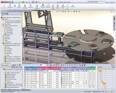
 Easily simulate complex machine operations using event-based motion analysis with SOLIDWORKS Simulation and validate the sequencing of the design to ensure correct operation, product quality, and safety. See how your product would move in the real world and measure the forces and loads while you design, helping you correctly size the motors and the structure and confirm the timing.
Tightly integrated with SOLIDWORKS CAD, event-based motion analysis using SOLIDWORKS Simulation can be a regular part of your design process—reducing the need for costly prototypes, eliminating rework or delays, and saving time and development costs.
Event-Based Motion Analysis Overview
In many cases, machine operation is based on triggers and sensors that activate machine action, such as a parcel being automatically sorted. Event-based motion is a complementary approach to solving kinematic and dynamic rigid body problems using SOLIDWORKS Motion, and has been developed to meet the needs of today’s more complex machine designs.
Event-based motion analysis is a solution method for rigid body motion where external actions (forces motion drivers) are triggered by the movement or the state of the assembly, rather than the time of the analysis. This approach has great advantages in the early stages of a design when product timings are not yet finalized.
Event-based motion can solve either kinematic or dynamic rigid body motion problems, and can simulate the effect of:
- Forces
- Springs
- Dampers
- Gravity
- Contact between components
- Bushings
Once the assembly motion has been calculated, a structural analysis of the components under the motion induced loads (accelerations and joint forces) can easily be carried out, either within the motion study or exported to a structural analysis study.
 Structural analysis for assemblies with SOLIDWORKS Simulation enables engineers to efficiently analyze product behavior under mechanical conditions taking into account the physical relationships between the parts of the structure to ensure high quality, performance, and safety.
Tightly integrated with SOLIDWORKS CAD, structural analysis of assemblies can be a regular part of your design process, reducing the need for costly prototypes, eliminating rework and delays, and saving time and development costs.
Assembly Structural Analysis Overview
Every product is made of several parts or bodies. Defining how these parts interact and connect to each other is crucial for an accurate structural simulation during the product development process.
Contacts
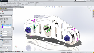
SOLIDWORKS Simulation supports contact conditions for studies of assemblies and multi-bodies. The contact settings describe the interaction between part boundaries that are initially contacting or come into contact during loading. To accurately describe these interactions, SOLIDWORKS Simulation offers several types of contacts, such as:
- Bonded contact conditions to simulate entities as if they were welded
- Node-to-node, surface-to-surface conditions to prevent entities interference, but allows gaps to form
- Self-contact conditions for contact between faces of a body or part in large deflection analysis
- Shrink Fit, to simulate Shrink Fit between two bodies
- Virtual Wall to define contact between an entity and a virtual wall
- Thermal contact resistance to simulate a thin layer of epoxy by its resistivity
To enable fast definition of contact for large assemblies, SolidWorks Simulation automatically detects contact sets for touching faces or non-touching faces within a defined clearance.
With an intuitive color code, engineers can inspect all contacts created in the model with the Contact Visualization Plot. This tool enables you to easily understand how an assembly has been defined for structural simulation.
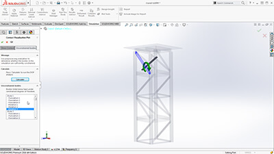 Unconstrained Bodies
In an assembly analysis, users define contact and boundary conditions to accurately describe the environment and real world conditions of the product design.
SOLIDWORKS Simulation guides product engineers through the analysis settings with the Unconstrained Bodies detection tool so they can verify that bodies are sufficiently constrained.
In a static study, users can view animations of the model based on the active degrees of freedom, and easily identify bodies that are under-constrained before running a simulation.
 Connectors
Products are also made with physical connections, such as bolts, springs, and welds between the parts of the assembly. SolidWorks Simulation offers sophisticated representations of these connections that simulate their behavior without having to create the detailed geometry. A connector is a mechanism that defines how an entity is connected to another entity or to the ground, such as: bolt, spring, pin, edge and spot weld and bearing.
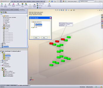
Powerful tools such as the Safety Check empower engineers to validate if the connections will sustain the applied loads or if these connectors need resizing for performance and quality.
To speed up the simulation setup and leverage the 3D CAD data, product engineers can automatically convert SolidWorks Toolbox fasteners that exist in a model to Simulation bolt connectors. Automatically the bolt connections are defined with their properties, such as location, diameter, and materials.
 Submodeling
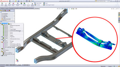
For an assembly with a large number of parts or bodies, the unique and powerful submodeling feature of SolidWorks Simulation Professional allows users to improve the results at critical areas without having to rerun the analysis for the whole model. Refining the mesh for a selected portion of the model and/or defining connectors for this portion and rerunning the analysis only for the submodel saves computation time during the product development process.
Perform structural optimization analysis during design using CAD-embedded SOLIDWORKS Simulation to reach the best available strength-to-weight, frequency, or stiffness performance for your designs, and cut costly prototypes, eliminate rework and save time and development costs.
Structural Optimization Overview
SOLIDWORKS Simulation simplifies structural optimization with a goal-driven design approach to parametrically alter a design so that it meets defined structural goals. You specify design goals at the beginning of design to:
- Have SOLIDWORKS software alert you during the design process if goals are violated
- Use goals in a design study where SOLIDWORKS Simulation automatically changes allowable model dimensions to maximize or minimize adherence to the design goal
Structural optimization uses multiple constraints to limit the scope of the optimization process, ensuring that any design study optimization meets the primary design goal without violating the supporting design requirements.