


Simulation Visualization Results, Reporting, and Customization
Evaluate and compare design alternatives with the visualization and reporting capabilities of SOLIDWORKS Simulation. Increase your ability to make informed design decisions while you ensure product performance and safety.
Tightly integrated with SOLIDWORKS CAD, SOLIDWORKS Simulation analysis visualization and reporting can be a regular part of your design process—helping to reduce the need for costly prototypes, eliminate rework or delays, and save time and development costs.
Simulation Visualization
The ultimate objective of virtual simulation is to get valuable information so you can quickly compare design alternatives—and identify the best.
SOLIDWORKS Simulation and SOLIDWORKS Flow Simulation offer a wide range of powerful and intuitive post processing tools, so you can get full value and understanding from your simulation data:
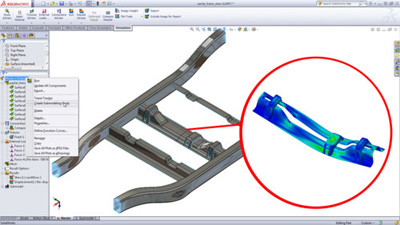
- Visualize the stress and displacement of your assembly with customizable 3D plots
- Animate the response of your assembly under loads to visualize:
- Deformations
- Vibration modes
- Contact behavior
- Optimization alternatives
- Flow trajectories
- Visualize SOLIDWORKS Simulation results on the full geometry for symmetrical models, instead of only a section of the model, giving you better insight on the model behavior
- Understand the fluid flow inside your products using the section plots, simply defined with any SOLIDWORKS plane
- Get values quickly and easily for critical parameters, such as pressure drop, using the Engineering Goals
- Investigate your design performance and isolate critical areas by results values, using the Isosurfaces plot
- Visualize the Fluid Flow results with real time interaction with the rendered, evenly spaced surface stream lines and the dynamic vectors
- Mirror results about Planes of symmetry
- Flow streamlines and dynamic vectors
Results Customization
SOLIDWORKS Simulation provides the standard results components for a structural analysis: Von Mises stresses, displacements, temperature, etc.
Product Engineers also can create Simulation result plots defined with equations using standard mathematical functions of existing result variables in order to address customized company or market standards.
The intuitive equation-driven result plot enables SOLIDWORKS Simulation users to customize the post processing of structural analysis for an even better understanding and interpretation of product behavior.
Simulation Communication and Reporting
Simulation results are now used to provide technical and business insights for product development decisions. In order to expand the understanding and use of Simulation results by all, SOLIDWORKS Simulation and SOLIDWORKS Flow Simulation provide an intuitive toolkit to communicate simulation results to Product Development stakeholders
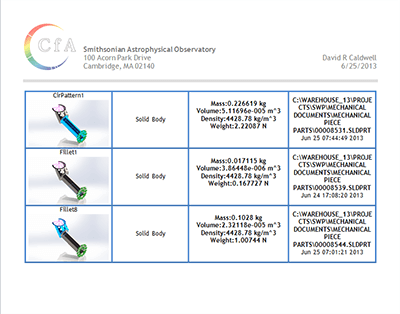 Create and publish customized reports in Microsoft.
- Communicate your simulation results and collaborate easily witheDrawingsYou can leverage the power of 3D vizualization to present Simulation results so they become powerful assets for business and technical decisions.
Assembly Analysis
Structural analysis for assemblies with SOLIDWORKS Simulation enables engineers to efficiently analyze product behavior under mechanical conditions taking into account the physical relationships between the parts of the structure to ensure high quality, performance, and safety.
Tightly integrated with SOLIDWORKS CAD, structural analysis of assemblies can be a regular part of your design process, reducing the need for costly prototypes, eliminating rework and delays, and saving time and development costs.
Assembly Structural Analysis Overview
Every product is made of several parts or bodies. Defining how these parts interact and connect to each other is crucial for an accurate structural simulation during the product development process.
SOLIDWORKS Simulation supports contact conditions for studies of assemblies and multi-bodies. The contact settings describe the interaction between part boundaries that are initially contacting or come into contact during loading. To accurately describe these interactions, SOLIDWORKS Simulation offers several types of contacts, such as:
- Bonded contact conditions to simulate entities as if they were welded
- Node-to-node, surface-to-surface conditions to prevent entities interference, but allows gaps to form
- Self-contact conditions for contact between faces of a body or part in large deflection analysis
- Shrink Fit, to simulate Shrink Fit between two bodies
- Virtual Wall to define contact between an entity and a virtual wall
- Thermal contact resistance to simulate a thin layer of epoxy by its resistivity
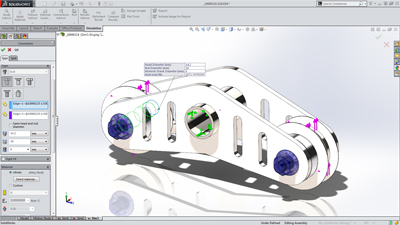
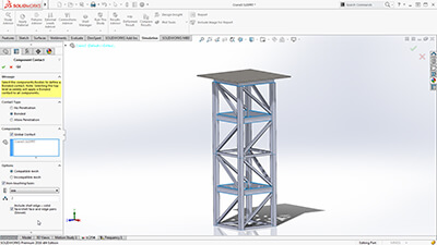
To enable fast definition of contact for large assemblies, SolidWorks Simulation automatically detects contact sets for touching faces or non-touching faces within a defined clearance.
With an intuitive color code, engineers can inspect all contacts created in the model with the Contact Visualization Plot. This tool enables you to easily understand how an assembly has been defined for structural simulation.
Unconstrained Bodies
In an assembly analysis, users define contact and boundary conditions to accurately describe the environment and real world conditions of the product design.
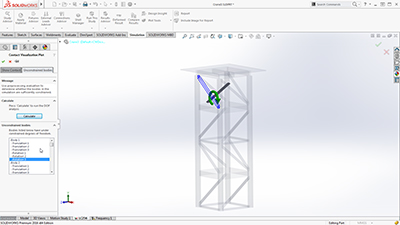
SOLIDWORKS Simulation guides product engineers through the analysis settings with the Unconstrained Bodies detection tool so they can verify that bodies are sufficiently constrained.
In a static study, users can view animations of the model based on the active degrees of freedom, and easily identify bodies that are under-constrained before running a simulation.
Connectors
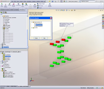
Products are also made with physical connections, such as bolts, springs, and welds between the parts of the assembly. SolidWorks Simulation offers sophisticated representations of these connections that simulate their behavior without having to create the detailed geometry. A connector is a mechanism that defines how an entity is connected to another entity or to the ground, such as: bolt, spring, pin, edge and spot weld and bearing.
Powerful tools such as the Safety Check empower engineers to validate if the connections will sustain the applied loads or if these connectors need resizing for performance and quality.
To speed up the simulation setup and leverage the 3D CAD data, product engineers can automatically convert SolidWorks Toolbox fasteners that exist in a model to Simulation bolt connectors. Automatically the bolt connections are defined with their properties, such as location, diameter, and materials.
 Efficiently optimize and validate each design step using fast-solving, CAD integrated SOLIDWORKS Simulation to ensure quality, performance, and safety.
Tightly integrated with SOLIDWORKS CAD, SOLIDWORKS Simulation solutions and capabilities can be a regular part of your design process—reducing the need for costly prototypes, eliminating rework and delays, and saving time and development costs.
Finite Element Modeling
SOLIDWORKS Simulation uses the displacement formulation of the finite element method to calculate component displacements, strains, and stresses under internal and external loads. The geometry under analysis is discretized using tetrahedral (3D), triangular (2D), and beam elements, and solved by either a direct sparse or iterative solver. SOLIDWORKS Simulation also offers the 2D simplification assumption for plane stress, plane strain, extruded, or axisymmetric options. SOLIDWORKS Simulation can use either an h or p adaptive element type, providing a great advantage to designers and engineers as the adaptive method ensures that the solution has converged.
In order to streamline the model definition, SOLIDWORKS Simulation automatically generates a shell mesh (2D) for the following geometries:
- Sheet metal body—SOLIDWORKS Simulation assigns the thickness of the shell based on the 3D CAD sheet metal thickness, so Product Designers can leverage the 3D CAD data for Simulation purposes.
- Surface body
For shell meshing, SOLIDWORKS Simulation offers a productive tool, called the Shell Manager, to manage multiple shell definitions of your part or assembly document. It improves the workflow for organizing shells according to type, thickness, or material, and allows for a better visualization and verification of shell properties.
SOLIDWORKS Simulation also offers the 2D simplification assumption for plane stress, plane strain, extruded, or axisymmetric options.
Product Engineers can simplify structural beams to optimize performance in Simulation to be modeled with beam elements. Straight, Curved, and tapered Beams are supported. SOLIDWORKS Simulation automatically converts structural members that are created as weldment features in 3D CAD as beam elements for quick setup of the simulation model.
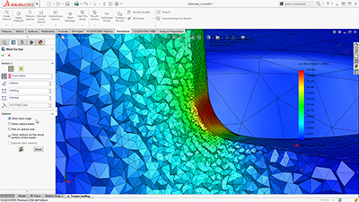
SOLIDWORKS Simulation can use either an h or p adaptive element type, providing a great advantage to designers and engineers, as the adaptive method ensures that the solution has converged. Product Engineers can review the internal mesh elements with the Mesh Sectioning Tools to check the quality of the internal mesh and make adjustments to mesh settings before running the study.
Users can specify local mesh control at vertices, edges, faces, components, and beams for a more accurate representation of the geometry.
Integrated with SOLIDWORKS 3D CAD, finite element analysis using SOLIDWORKS Simulation knows the exact geometry during the meshing process. And the more accurately the mesh matches the product geometry, the more accurate the analysis results will be.
Finite Element Analysis (FEA)
Since the majority of industrial components are made of metal, most FEA calculations involve metallic components. The analysis of metal components can be carried out by either linear or nonlinear stress analysis. Which analysis approach you use depends upon how far you want to push the design:
- If you want to ensure the geometry remains in the linear elastic range (that is, once the load is removed, the component returns to its original shape), then linear stress analysis may be applied, as long as the rotations and displacements are small relative to the geometry. For such an analysis, factor of safety (FoS) is a common design goal.
- Evaluating the effects of post-yield load cycling on the geometry, a nonlinear stress analysis should be carried out. In this case, the impact of strain hardening on the residual stresses and permanent set (deformation) is of most interest.
The analysis of nonmetallic components (such as, plastic or rubber parts) should be carried out using nonlinear stress analysis methods, due to their complex load deformation relationship. SOLIDWORKS Simulation uses FEA methods to calculate the displacements and stresses in your product due to operational loads such as:
- Forces
- Pressures
- Accelerations
- Temperatures
- Contact between components