


Nonlinear stress analysis with SOLIDWORKS Simulation enables designers and engineers to quickly and efficiently analyze stresses and deformations under general conditions while they are creating their design to ensure high quality, performance, and safety.
Tightly integrated with SOLIDWORKS CAD, nonlinear stress analysis using SOLIDWORKS Simulation can be a regular part of your design process. You can use the Simulation results to validate your part or assembly while you are designing, reducing the need for costly prototypes, eliminating rework and delays, and saving time and development costs.
Nonlinear Stress Analysis Overview
Nonlinear stress analysis calculates the stresses and deformations of products under the most general loading and material conditions for:
- Dynamic (time dependent) loads
- Large component deformations
- Nonlinear materials, such as rubber or metals, beyond their yield point
Nonlinear analysis is a more complex approach, but results in a more accurate solution than linear analysis, if the basic assumptions of a linear analysis are violated. If the linear analysis assumptions are not violated, then the results of a linear and nonlinear analysis will be the same.
The time component when carrying out a nonlinear analysis is important, both in controlling the loading (individual load components can be active at different times) and in capturing the response to an impulse load of impact. SOLIDWORKS Simulation provides either an automatic or a manual time control method with a force, displacement, or arc length convergence control. You get power and flexibility to solve challenging and complex simulation problems simply in a straightforward manner.
SOLIDWORKS Simulation uses finite element analysis (FEA) methods to discretize design components into solid, shell, or beam elements and uses nonlinear stress analysis to determine the response of parts and assemblies due to the effect of:
- Forces
- Pressures
- Accelerations
- Temperatures
- Contact between components
Loads can be imported from thermal and motion Simulation studies to perform multiphysics analysis.
In order to carry out stress analysis, component material data must be known. The standard SOLIDWORKS CAD material database is pre-populated with materials that can be used by SOLIDWORKS Simulation, and the database is easily customizable to include your particular material requirements.
While the Nonlinear Analysis is solving, you can visualize intermediate results. By getting visual feedback of the results as the solution progresses, you can make decisions to either stop the simulation and make adjustments to the input, or let the solver proceed with the current settings.
The Load Case Manager with SOLIDWORKS Simulation enables designers and engineers to quickly and efficiently analyze stresses and deformations under general conditions while they create their design for high quality, performance, and safety.
Loads Overview
Loads and restraints are needed to define the service environment for the model. Analysis results directly depend on the specified loads and restraints. The defined loads and restraints are applied to geometric entities as features that are fully associative to the geometry and that automatically adjust to geometric changes.
The types of loads available depend on the type of the study defined. You can apply to your model:
- Pressure (uniform or variable along Cartesian, Cylindrical, and Spherical Coordinates systems)
- Force, moments or torque (uniform or variable along Cartesian, Cylindrical, and Spherical Coordinates systems)
- Gravity (linear accelerations)
- Centrifugal force (angular velocity and acceleration)
- Remote loads
- Bearing loads (between contacting cylindrical faces)
- Temperature
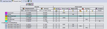 Load Case Manager Overview
The Load Case Manager allows product engineers to define secondary load combinations from primary load definitions quickly and evaluate the effects of the various load combinations on the model. Users can then evaluate their design for multiple load cases.
For example, you can combine wind loads and snow loads in a single model with a user defined equation.
You can create SOLIDWORKS sensors to track specific results for all load cases (primary and secondary), as well as view all the results for primary and secondary load cases.
 Efficiently optimize and validate each design step using fast-solving, CAD integrated SOLIDWORKS Simulation to ensure quality, performance, and safety.
Tightly integrated with SOLIDWORKS CAD, SOLIDWORKS Simulation solutions and capabilities can be a regular part of your design process—reducing the need for costly prototypes, eliminating rework and delays, and saving time and development costs.
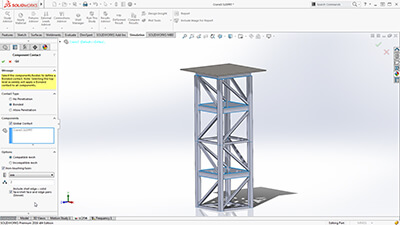
Finite Element Modeling
SOLIDWORKS Simulation uses the displacement formulation of the finite element method to calculate component displacements, strains, and stresses under internal and external loads. The geometry under analysis is discretized using tetrahedral (3D), triangular (2D), and beam elements, and solved by either a direct sparse or iterative solver. SOLIDWORKS Simulation also offers the 2D simplification assumption for plane stress, plane strain, extruded, or axisymmetric options. SOLIDWORKS Simulation can use either an h or p adaptive element type, providing a great advantage to designers and engineers as the adaptive method ensures that the solution has converged.
In order to streamline the model definition, SOLIDWORKS Simulation automatically generates a shell mesh (2D) for the following geometries:
- Sheet metal body—SOLIDWORKS Simulation assigns the thickness of the shell based on the 3D CAD sheet metal thickness, so Product Designers can leverage the 3D CAD data for Simulation purposes.
- Surface body
For shell meshing, SOLIDWORKS Simulation offers a productive tool, called the Shell Manager, to manage multiple shell definitions of your part or assembly document. It improves the workflow for organizing shells according to type, thickness, or material, and allows for a better visualization and verification of shell properties.
SOLIDWORKS Simulation also offers the 2D simplification assumption for plane stress, plane strain, extruded, or axisymmetric options.
Product Engineers can simplify structural beams to optimize performance in Simulation to be modeled with beam elements. Straight, Curved, and tapered Beams are supported. SOLIDWORKS Simulation automatically converts structural members that are created as weldment features in 3D CAD as beam elements for quick setup of the simulation model.
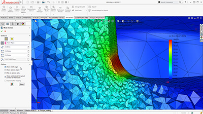 SOLIDWORKS Simulation can use either an h or p adaptive element type, providing a great advantage to designers and engineers, as the adaptive method ensures that the solution has converged. Product Engineers can review the internal mesh elements with the Mesh Sectioning Tools to check the quality of the internal mesh and make adjustments to mesh settings before running the study.
Users can specify local mesh control at vertices, edges, faces, components, and beams for a more accurate representation of the geometry.
Integrated with SOLIDWORKS 3D CAD, finite element analysis using SOLIDWORKS Simulation knows the exact geometry during the meshing process. And the more accurately the mesh matches the product geometry, the more accurate the analysis results will be.
Finite Element Analysis (FEA)
Since the majority of industrial components are made of metal, most FEA calculations involve metallic components. The analysis of metal components can be carried out by either linear or nonlinear stress analysis. Which analysis approach you use depends upon how far you want to push the design:
- If you want to ensure the geometry remains in the linear elastic range (that is, once the load is removed, the component returns to its original shape), then linear stress analysis may be applied, as long as the rotations and displacements are small relative to the geometry. For such an analysis, factor of safety (FoS) is a common design goal.
- Evaluating the effects of post-yield load cycling on the geometry, a nonlinear stress analysis should be carried out. In this case, the impact of strain hardening on the residual stresses and permanent set (deformation) is of most interest.
The analysis of nonmetallic components (such as, plastic or rubber parts) should be carried out using nonlinear stress analysis methods, due to their complex load deformation relationship. SOLIDWORKS Simulation uses FEA methods to calculate the displacements and stresses in your product due to operational loads such as:
- Forces
- Pressures
- Accelerations
- Temperatures
- Contact between components
Loads can be imported from thermal, flow, and motion Simulation studies to perform multiphysics analysis.
Mesh definition
SOLIDWORKS Simulation offers the capability to mesh the CAD geometry in tetrahedral (1st and 2nd order), triangular (1st and 2nd order), beam, and truss elements. The mesh can consist of one type of elements or multiple for mixed mesh. Solid elements are naturally suitable for bulky models. Shell elements are naturally suitable for modeling thin parts (such as sheet metals), and beams and trusses are suitable for modeling structural members.
As SOLIDWORKS Simulation is tightly integrated inside SOLIDWORKS 3D CAD, the topology of the geometry is used for mesh type:
- Shell mesh is automatically generated for sheet metal model and surface bodies
- Beam elements are automatically defined for structural members
So their properties are seamlessly leveraged for FEA.
To improve the accuracy of results in a given region, the user can define Local Mesh control for vertices, points, edges, faces, and components.
SOLIDWORKS Simulation uses two important checks to measure the quality of elements in a mesh:
- Aspect Ratio Check
- Jacobian Points
In case of mesh generation failure, SOLIDWORKS Simulation guides the users with a failure diagnostics tool to locate and resolve meshing problems. The Mesh Failure Diagnostic tool renders failed parts in shaded display mode in the graphics area.