


Easily investigate the impact of cooling and design changes on component temperatures using thermal fluid analysis in SOLIDWORKS Flow Simulation. You can quickly determine the impact of fluids flowing in and around the design to ensure correct thermal performance, product quality, and safety.
Tightly integrated with SOLIDWORKS CAD, thermal fluid analysis using SOLIDWORKS Flow Simulation can be a regular part of your design process—reducing the need for costly prototypes, eliminating rework or delays, and saving time and development costs.
Thermal Fluid Analysis Overview
Thermal fluid analysis enables analysis of conjugate heat transfer (thermal conduction in solids, convection between fluid and solid, and radiation) using computational fluid dynamics (CFD) so you can:
- Detect hot spots in their designs
- Reduce overheating challenges
- Improve thermal isolation
- Leverage thermal performance in their products
SOLIDWORKS Flow Simulation calculates either the steady state or transient temperature fields due to:
- Heat transfer in solids (conduction)
- Free, forced, and mixed convection
- Radiation
- Heat sources (heat generation rate, heat power, temperature)
Temperature fields can be exported to SOLIDWORKS Simulation for a thermal stress analysis.
 Quickly understand complex component responses with analysis of composite parts using SOLIDWORKS Simulation. You can then optimize material selection and the number and orientation of the composite ply layup to ensure product quality, performance, and factor of safety (FoS).
Tightly integrated with SOLIDWORKS CAD, analysis of composite parts using SOLIDWORKS Simulation can be a regular part of your design process, reducing the need for costly prototypes, eliminating rework and delays, and saving time and development costs.
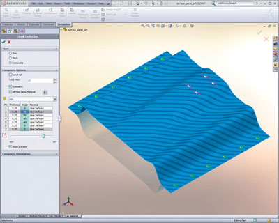
Analysis of Composite Parts Overview
Easily analyze symmetrical and unsymmetrical composite layups, as well as composite sandwiches, with SOLIDWORKS Simulation. Each layer can be defined by a unique set of material properties and orientation, giving the designer maximum control to find the optimum layup and material for maximum product performance.
The failure criterion for composite materials is very different than for metals. Composite materials do not yield; rather, the fibers delaminate and fracture. SOLIDWORKS Simulation reports the FoS against failure according to the Tsai-Wu and Tsai-Hill failure indexes.
SOLIDWORKS Simulation uses finite element analysis (FEA) methods to discretize composite components into shell elements and uses stress analysis to determine the response of parts and assemblies due to the effect of:
- Forces
- Pressures
- Accelerations
- Temperatures
- Contact between components
- Fiber delamination
 Dynamic analysis using SOLIDWORKS Simulation enables designers and engineers to quickly and efficiently determine the impact of time varying loads on the structural response of their product design to ensure performance, quality, and safety.
Tightly integrated with SOLIDWORKS CAD, dynamic analysis using SOLIDWORKS Simulation can be a regular part of your design process, reducing the need for costly prototypes, eliminating rework and delays, and saving time and development costs.
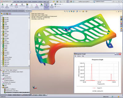
Dynamic Analysis Overview
Dynamic analysis can incorporate frequency, impact, and drop tests. The primary unknown in a dynamic analysis is component displacement over time, but with this calculated, stresses, velocities, and accelerations can also be determined together with the natural modes of vibration.
SOLIDWORKS Simulation uses one of two methods for dynamic analysis:
- Linear modal analysis determines the natural modes of vibration and then the displacements, stresses, strains, velocities, and accelerations.
- Nonlinear dynamic analysis calculates the displacement field at every time step, given the applied loads and initial component velocities. From this field, the nonlinear stresses, strains, velocities, and accelerations are calculated.